The 10 stud cylinder head has stock size valves, alloy bronze guides (probably aluminum bronze) and stock valve springs. The spring heights are carefully set to fitted length. The spring retainers are lightened. No material was removed from ports. Adaptors for the MK2 Amals are made in house from aluminum plate and tube. Rocker gaskets are not used as there is no oil feed to the top end. One drop of Castrol R per valve, per race is what the guides survive on.
The combustion chamber is standard and shows some battle scars from a previous life. The surface was lightly skimmed on the lathe in the workshop at home. The tube in the inlet manifold is for MAP sensor and data logging.
Clutch components came under some attention. Basically it's stock set up with belt drive outer wheel.
The shock absorber is lightened on it's outer cover. The inner flange is hardened steel though a build up with wear-braze solved its' wear issues. It's through bolted and loctited. The smaller washer goes under the main washer to make for solid push on the taper. Otherwise the main washer can "bow" like a spring.
Update: the belt drive has been swapped out for a duplex chain set up.
Selected top end fasteners. Necked or through drilled. Alloy washers are 7075 T6. Far left are the head "tube nuts", made from 7075 T6 aircraft alloy. Their hex is broached in a press using an allen key socket as the broach.
Regular 10 stud barrel with fins cut off. Saved a few KG! Here, freshly painted. The follower blocks have oil return holes plugged with resin. Size is +.060.
The long screws on the left are the engine crankcase throughbolts. These are allen head with 7075 T6 flange nuts and washers. Screws to the right are timing cover and other crankcase fasteners, necked and/or reduced heads. The tubes at the top are the sleeves for the slim engine mount bolts. Pushlok plastic fitting is the blanking plug for the oil pressure port in the timing cover.
Timing cover had a small amount of alloy removed from around the center spindle boss. The oil pump had casting flashings polished of with a bit of rounding to the piston uppers. Hollowing out of the oil pump pistons is a possibility for the future.
Pistons and rings are +060 hepolites with standard compression ratio. Some smoothing to the crown plus inlet valve pockets deepened. Also they have had a small amount of material removed from the squish to restore piston to head clearance of 1mm. Intermediate wheel got a light polishing and retains the full weight. The two spools to the top right are the lower engine mount spacers, machined from solid 7075 T6.
This is how the barrels looks are two seasons of dragracing. All looks in very good shape so will be re-used as is. After all it's only done about 120 miles!
The cam follower block has the drain holes plugged with a two-pack resin to stop the oil coming up. Pushrod towers aren't used so the pushrods are totally exposed to atmosphere. The plastic tubes are simply to stop the followers falling out when the motor is apart.
This is the crank used for the two seasons. It's -030 on the bigends. It's a mid 60's 650 crankshaft with one of the lighter flywheel options. The timing side main has a sleeve to adapt to the metric bearing used on later 650/750s. The conrods were new/old stock two years ago. The plan is to swap out the crank for a 750 item with full flywheel weight as per standard. Engine size will remain 773cc.
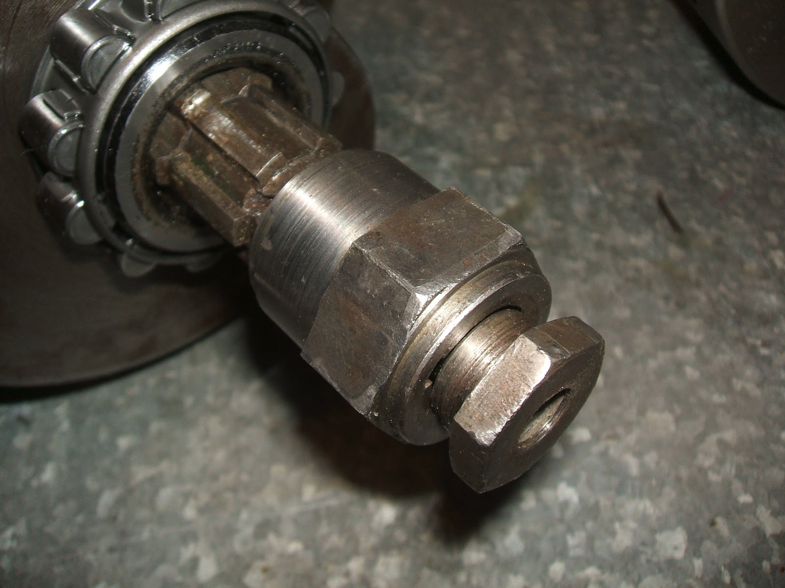
This hex on the end of the crank is for the remote starter drive. It's the core of a Lucas alternator rotor which is keyed to the shaft as per standard. The nut secures it in the normal fashion and in this case, being an early crank, is cycle thread.
Rear mounting plates plus top head steady with fasteners and spacers. The steady is made from lightweight aluminum channel. A trial this coming season will be to swap out the steady for a steel replacement to assess for any improvement in vibration.
Stock pushrods were carefully tapered and linished on the steel endcups.
This view shows the inlet manifolds which are made from tube and plate, welded then lathed flat on the gasket surface. The groove was carefully machined to match the Mk2 carb rubber. A mistake in making these has to do with the carb rubber bore. It's doesn't give the correct size for the 30mm throat so small spacers were made as an afterthought. These should have been made as part of the mainfold!
Combustion chamber. Stock size valves, using the so called chrome stem variety from Hyde.
Stock top collars were scallop lightened. Stock valve springs were carefully set at factory fitted length spec. Valves were polished on the heads to a good luster.
These no oil feed here as such. The valves and guides survive on a single drop each per drag race run, an elapsed time in total of 4 minutes including 'warming' the tire, staging and riding back on the slip road.
The view of the valve through the inlet manifold port. Ports are matched to manifolds with careful metal removal. No material was otherwise taken from the inlet tracks.
Gearbox fasteners. The 7075 T6 sleeve replaces the kickstart rachet.
This is the stay for clamping the header pipes into place. The spring allows for header expansion.
Closeup of the spring and nut. This stay was made from an old spoke.
The timing chest shows intermediate spindle hollowed. It has the regular oil hole for the bush and is plugged at the far end. Camwheels are the full weight 750 type and add to flywheel weight.
Ignition taper drive for the mk3 Boyer electronic. The taper was brazed on and forms part of the lefthand threaded nut. The thread you see has been drilled and tapped 1/4UNF into the T140 inlet cam. (Remember... the carbs are at the front of the engine!!).
Another timing chest view. If I recall the intermediate spindle is machined from silver steel, or else it was a stock shaft drilled out using a re-sharpened tungsten tip masonary bit.
Five speed camplate showing drilled out center. To play it safe, this end is drilled bigger diameter than the other end due to the way it's rivetted.
Replacing the original steel item is this clutch cable adapter. It threads into the case and is made from... you guessed it ... 7075
Hollowed out gearchange shaft. It's hollowed out at various diameters due to the way it's made. A good amount of weight was saved!! (I wish I'd measured it)
Old kickstart shaft hole is plugged with possibly the free machining alloy I had at the time. The gearbox filler cap above is a plastic bung from a polyethylene drum.
Clutch parts. Spring nuts are made from 7075. The main nut is stock as is the washer. The washer to the right fits under the stock washer, into the recess made for the puller thread. This helps give a much more "solid push" for the main nut and makes the tapers' hold stronger. (See one of my Youtube videos for a better look.)
Crankshaft timing side end. The spacer (pictured) was needed to bring the crank into line and make the rods central in their bores. This must be the difference between the early pre '72 imperial t/s bearing cranks and the later metric bearing'd equivalents.
The two crankcase studs have been wasted and their ends dimpled with a center drill bit. The LH main bearing tunnel has been in the wars from a previous life. It's had a peening at some stage and it's a touch too loose a fit.
The gearbox studs are wasted down to "thread depth" as I reason that the stud is only as strong as its' smallest diameter, which is the root diameter of the thread.... so the stud may as well be turned down to that diameter. The camplate detent fitting came in for some pruning as well.
The T140 inlet on the left (at the front of engine) and the T120 exhaust have been lightly linished to removed casting numbers and irregularities. These were hardness tested using the Rockwell scale by local Toolmakers. The cam bushes were found to be loose when I first built the motor in 2010 so I copper plated them to the required interference fit. I have a homemade copper plating setup powered by a battery charger.
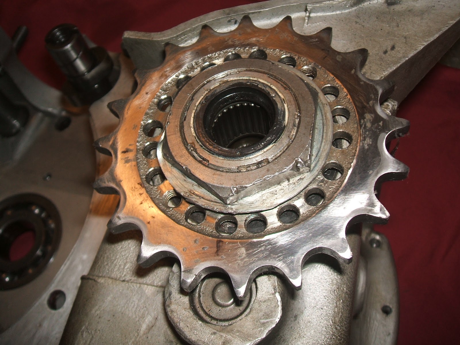
This sprocket has been lightened using a re-sharpened masonary drill bit. The skin on the sprocket was so super hard! Drilling was by a cheapo drillpress. The bits squeal like mad but they eventually get through. It's narroweed to 520 chain size.
These gearbox bits were used for the two seasons and it was subsequently found that the quadrant is cracked so it will be replaced. The selector plate and screw have been on a serious diet! The part on the right has an extra lightening hole drilled between the pawl tunnels.
The shaft is the selector shaft, an original hollowed out with tungsten tip drill bit. Again this shaft is hard skinned, but inside it's soft enough for regular bits. The selectors had minor dags and casting flashings linished off.
These pair are what I use to match the mk2 carb rubbers to the 30mm carbs and the 30mm manifolds. As I said earlier, these pieces should have been machined on the mainfold itself.
Here is where I drilled the housing. This where earlier models had a speedo drive so it's quite a solid lump at this point.
The spindle (pictured) is what I made for the quadrant pivot however I'm reviewing this due to occasional gearchange issues. The pin should turn with the quadrant!
Shortened custom hollow rocker spindles made from silver steel with alloy end cap and 6mm retaining screw. Rockers are slimmed and polished. Adjusters are allen head type. Locknuts are half height, slimmed down from the original cycle thread nuts. Rocker spacers are machined to fit from 7075 alloy with as little endfloat as possible. (There is no oil feed to the top end)
Gearbox parts. Top left are alloy nuts and washers replacing the 2 chrome dome nuts on the outer cover. To its' right are 8mm titanium gbox mounting bolts and nuts. Below those are the wasted allenhead screws. The item on the left is the drain plug which is hollowed from underneath.
The two main engine bolts. Both are 8mm and fit using alloy sleeves. The longer is the lower mounting bolt and is made from high tensile threaded rod. The other is a cap screw for the from mount. Both nuts for these are captive in the frame.